
M4A3 conversion to an M51 Degum Gimel
by
Rick Wilkes
Rick Wilkes
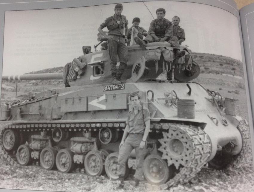
Being a big fan of IDF armor and in particular the M50/M51 Sherman’s, I always look forward to each new book in the Lioness & Lion of the Line series by Dr. Robert Manasherob. While reading Vol. 10 M51 Sherman Tanks of the Six Day War – Pt 1, I discovered it included pictures and drawings of the fairly rare conversion of a late M4A3 hull to and M51.
The tank pictured above from the third production batch of M51’s (Degum Gimel), indicated by the full stowage suite, spare track mounted on the turret and the reinforced muzzle brake. From my other references it appears that there were only 50 welded hull M4’s converted to M51’s, the rest built on big hatch M4A1 hulls.
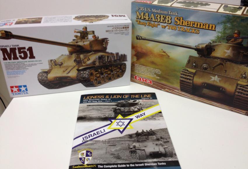
With all that going for it I knew I had to make one of my own. For the hull and suspension I’m using a Tasca M4A3E8 (kit 35-020), and for the turret, engine components, and part of the stowage, I’m using the Tamiya M51 (kit 35323).
Other parts came from my ever growing supply of Sherman spares, resin sets etc.
Basic Hull construction and Stowage
There are also various places where I do not follow the assembly sequence for adding subassemblies for ease of painting etc. I suspect we all have similar preferences, so when I say a step is “As Shown” it means I didn’t make any changes to the parts.
Building up the hull and suspension are basically per the Tasca instructions with the following changes.
Step 1: Not done since I am using Dragon DS T80 track to replace the T-66 track provided in the kit.
Step 2: Omit parts C74.
Step3: Omit parts C47, C74, O9, O10, O11, O12, O14, O15, O16, O17 & O18.
Reserve parts O1 & O8 for later use.
Modify part O6 by removing the ‘hinges” for the engine doors, and fill & sand smooth the hole for the right hand exhaust.
Steps 5 & 6: Assemble as shown, install per personal preference.
Step 7: Assemble as shown, except omit parts O2 and fill the mounting slots.
The sharp eyed among you may notice that I installed these and had to remove them later. Next scrounge a set of grouser vents and add them to the engine deck behind the rear lift rings, refer to your references for exact placement.
Step 8: As shown, I choose not to add the bow MG (C41), but will add a barrel
during final detailing.
Step 9: As shown.
Step 10: As shown except, omit parts C56, C57 & C58. Fill the mounting holes
for parts C56.
Step 11: Install the tail lights (parts C32 & C33) with their guards, ignore the rest.
Step 12: Install filler covers D4 & D7, ignore the rest.
Step 13: As shown, except use T80 track.
Step 14: Add the fenders (parts M16 & M17), position the braces (part B11) as
shown in your references. Do not install the spare track links.
Step 15: The storage rack and cleaning rods will be added following the installation on the new engine deck and the hinges for the gun travel lock.
That completes the basic hull assembly, No other parts from the Tasca kit are needed, the rest can go in your spare parts stash.
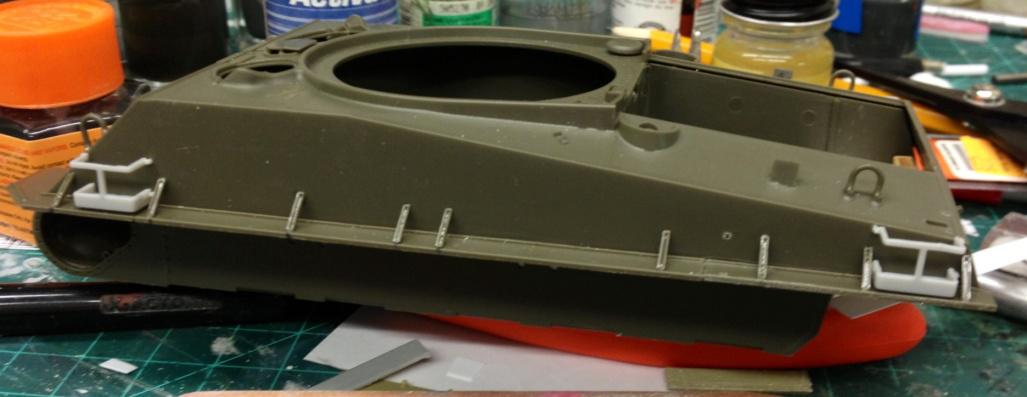
This photo shows the Tasca hull at the point where I began adding the stowage
suite. The jerry can holder’s are from a Dragon M50 kit, since several will be empty I chose to separate racks and choose plastic over resin for ease of installation. As you can see the fender braces fewer in number and relocated based on my reference.
suite. The jerry can holder’s are from a Dragon M50 kit, since several will be empty I chose to separate racks and choose plastic over resin for ease of installation. As you can see the fender braces fewer in number and relocated based on my reference.
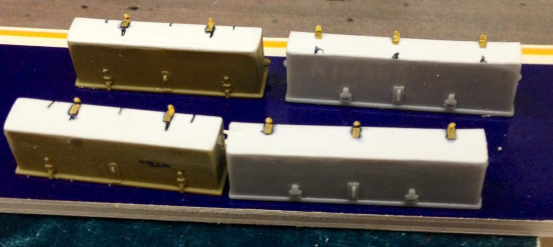
The side boxes are modified parts from the Dragon M50 & an Academy M51. The boxes are not the same length and fortunately the Dragon parts were correct for the “long” box & the Academy parts for the other. They were the right width but were too deep so I cut off the bottoms and replaced them with card stock.
The brass mounting hardware is from the Aber M50 set.
The rest of the stowage was gathered up from various sources and added to the hull as follows. Remember to use your references as individual tanks can vary.
The brass mounting hardware is from the Aber M50 set.
The rest of the stowage was gathered up from various sources and added to the hull as follows. Remember to use your references as individual tanks can vary.
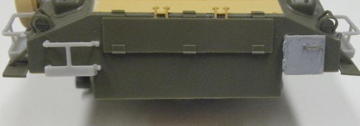
Front Plate
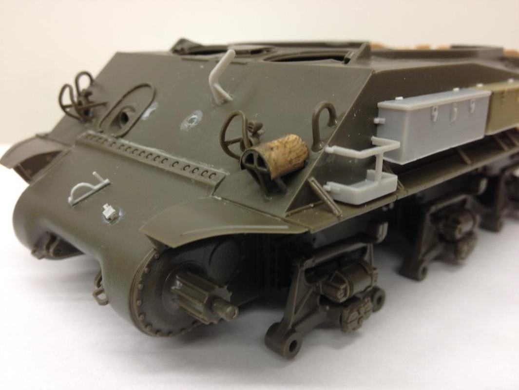
I added the L shaped wire hanger and the associated D-Clamp.
Next to the D-Clamp is the lower half of a cable clamp. Last I added a horn cover that is made of thin annealed sheet brass.
Next to the D-Clamp is the lower half of a cable clamp. Last I added a horn cover that is made of thin annealed sheet brass.
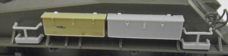
Left Side
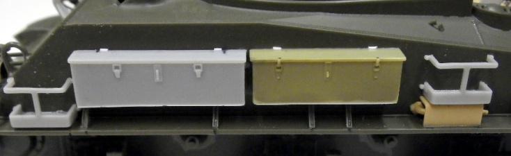
Here are the side boxes mounted. Unlike the M51’s built on M4A1 cast hulls, not as much “stand off” from the hull is required for the stowage items, I used disks punched out of .20 thou card stock on the jerry can racks, and butt joined the boxes but left the upper seam open. After painting I may need to run a fine scribe
along that seam to “open” it back up for visual effect.
along that seam to “open” it back up for visual effect.
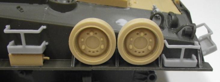
Farther along the left side parts from the Tamiya M51start coming into play.
Here you see the APU exhaust and shield (parts F24 & F24) and the
spare road wheels (parts F8 & F15).
Here you see the APU exhaust and shield (parts F24 & F24) and the
spare road wheels (parts F8 & F15).
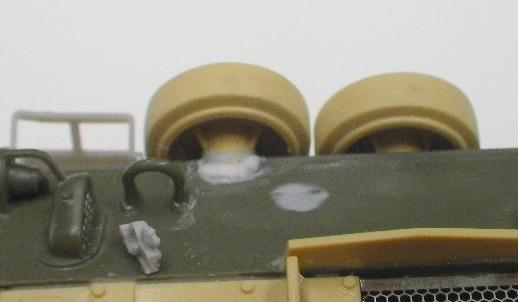
Below you can see the “weld” used for the back spare road wheel mount, another cable clamp, and the repair where I removed parts O2 installed in Step 7. Also note the grouser vent I added between the lift ring and the tail light. This is repeated on the right side. The presence of these vents as led to some “esoteric speculation” that perhaps this M51 is based on an M4(105mm Gun) hull, since the opening for these vents was eliminated on M4A3 hulls.
Upper Rear
I first made notches for and fitted the hinges for the gun travel lock from the Tamiya kit (parts F4) then mounted the upper half of the Tasca storage rack (part C46) from step 15. The jerry can rack and phone box are from the Dragon M50.
Right Side
A repeat of the left side installation, less the APU and spare road wheels.
That completes the basic hull and stowage construction phase of this conversion.
Tools, etc will be added later when I’m closer to the painting stage.
In the next installment I’ll cover the changes to the engine deck and lower hull required for the Cummins diesel power plant.
Questions, comments, etc., welcome.
Rick
