
Soldering Photoetch
By Andrew Albrecht
After hearing so many people praise the wonders of solder, I finally decided to give it a try over the holidays. It was a real surprise to see decent results almost from the beginning. If you ever wondered if soldering might be for you, you should definitely give it a try. If you feel comfortable working with photoetch in the first place, then soldering it probably won't pose any real difficulty. The cost of equipment is surprisingly cheap too. My cheap rig was more than up to the task. For about $20 you can get an inexpensive soldering iron, the flux, and solder. Most of the other tools I use are probably already in your toolbox.
Tools
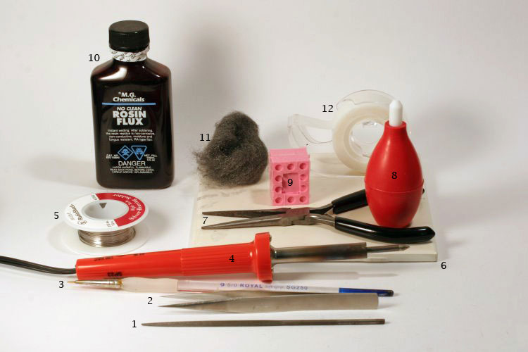
Listed below are the tools I find useful when soldering and a short explanation how I use them. Click on the photo (or any others) to see a larger view.
The only tool that might be hard to find is the RTV rubber scrap (#9). If someone in your club makes their own rubber molds they might have a mold reject. You don't need a very large piece but it helps if at least one edge is flat. I use it as a combination clamp/heat sink. You can press it down onto the PE to cover areas where you don't want the heat to build up. Or you can use it to hold parts in place. The flexibility keeps the etched parts from deforming under the pressure and the heat resistant properties of the rubber keep the etch cool. You can place the rubber fairly close to where the iron comes in contact with the metal but don't touch the iron directly to the rubber as it will burn. I haven't tested it, but a plastic eraser might work as well
- Triangular jewelers file. Removes excess solder quickly.
- Pointed tweezers. Useful for handling small PE and holding parts together while soldering.
- Fine tip paint brush - mine is a cheap 5/0 past its prime. Don't plan on using this brush for anything else after...
- Super cheap soldering iron. It's a 20 watt model with a large tip. I recommend one with a fine tip. The large tip on mine was a little challenge for really small PE. (RadioShack.com has models as low as $8)
- Small diameter flux-less solder and any diameter rosin core solder (not pictured). The flux-less solder I use (0.015") is called "Silver Solder" and comes from Radio Shack ($5). The use of these two types of solder is discussed below.
- Ceramic tile from the locale DIY. This serves as a good heat resistant base to work on.
- Smooth jawed pliers. Heat sink and clamp all in one.
- Solder bulb. Useful for removing some (but not all) solder from metal. Use it to suck up solder while it's still molten.
- Scrap piece of RTV Rubber (explained below).
- Rosin flux. Mine is a liquid similar to tree sap in consistency. I've heard paste types work just as well. (About $6)
- Extra fine steel wool. Removes crusted rosin and polishes PE and solder to a nice shine.
- Scotch tape. Extra "expendable" fingers.
- 6" metal rule (not pictured). Useful for holding parts in place.
- Damp sponge or wadded towel (not pictured). Useful for wiping off excess solder from the iron.
The only tool that might be hard to find is the RTV rubber scrap (#9). If someone in your club makes their own rubber molds they might have a mold reject. You don't need a very large piece but it helps if at least one edge is flat. I use it as a combination clamp/heat sink. You can press it down onto the PE to cover areas where you don't want the heat to build up. Or you can use it to hold parts in place. The flexibility keeps the etched parts from deforming under the pressure and the heat resistant properties of the rubber keep the etch cool. You can place the rubber fairly close to where the iron comes in contact with the metal but don't touch the iron directly to the rubber as it will burn. I haven't tested it, but a plastic eraser might work as well
Solder, maintenance, and prep
Solder is a low melting point alloy that bonds well to copper based metals. By applying relatively low heat the solder becomes molten liquid. Flux (usually rosin) is used to help the solder flow and has an additional duty as a cleaning agent. Solders that contain rosin (or some kind of "core") flow easily everywhere there is metal and enough heat. Solders that do not contain flux tend to stay put when melted. This property of rosin is what you exploit to get good results soldering PE. Use a rosin core solder on PE and you have an uphill battle contoling the solder flow. It will be very hard to keep solder from covering up detail and your joints will be huge silvery blobs. However, if you use carefully applied rosin flux and a core-less solder, you can prevent solder from getting into places you don't want it. I recommend practicing on some etch fret to see how the two types of solders behave before your first attempt on actual PE.
A quick word on maintenance: I recommend that you "tin" the iron's tip before each session, especially if it stays hot for extended periods. You will need to do this the first time you use the iron anyway because an untinned tip transfers heat poorly and solder tends to pool up on the iron rather than flow from it. Keep an eye out for the photo below that shows the solder pooling on my iron. To tin the tip, heat up the iron to temperature and apply just enough rosin core solder to lightly coat about 1/3 of the tip. If you get too much on, wipe the tip on the damp sponge or paper towel. Make sure the sponge or paper towel is damp when you do this or you could have a fire on your hands. Immediately after tinning, the first few applications of solder to PE might be on the heavy side so a little extra care is needed when you start.
As mentioned above, flux acts as a cleaning agent. I did not clean before soldering any of the parts in the article. Most people recommend cleaning the metal prior to soldering but I had good results without doing so. My rosin says "no clean" on the bottle so it could be a special property of my particular rosin. Testing with your own materials is strongly recommeneded. Also keep in mind that solder seems to only bond to copper based metals (copper, brass, bronze). Since most PE comes in brass this should be no problem unless you like Eduard PE. Some of their (older?) sets are coated with a corrosion resistant metal that apparently does not bond with solder. I've been told that you can remove the coating with fine sand paper or steel wool to get to the brass base metal but have not tried this personally. The failure to bond non-copper metals can actually be advantageous. The cylinder example below was soldered while wrapped around a steel drill bit. And the seam (exposing the steel underneath) was filled in with solder. After cooling, the cylinder simply popped off the bit. I've had similar "failures to bond" with aluminum and lead foil (the stuff from wine bottles).
The Victims
For this article I chose two examples, a simple cylinder and the rear flap of an Aber Pz IV fender. Rolling photoetch into cylinders is a common technique with many manufacturers and this also demonstrates solder's gap filling ability. The fender illustrates a multipart assembly with solder joints in close proximity to one another. It's also something that gets pretty damaged on the real thing and benefits greatly from a solder bond if you plan on replicating battle damage. I should note that the fender was actually a donor from another kit I'm working on. It was originally assembled with CA but I disassembled it for this article. Removing it from the kit and cleaning off the original CA of course damaged the parts in the process - there should be a Murphy's Law about super glue! Several parts broke into smaller pieces and a few parts were warped beyond repair. The final fender is slightly out of square as a result. If these parts had been fresh from the fret the fender would have turned out perfectly. As it stands, it still turned out pretty well.
Cylinders
For the cylinder, my goal was to make a tube 5mm in diameter and some arbitrary length. A quick search online turned up some important forgotten geometry: Circumference = Diameter * PI.
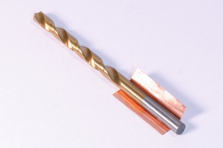
I multiplied my target diameter (5mm) by PI to arrive at 15.707963267948966... 16mm was close enough for me so I cut a piece of copper foil 16mm by roughly 50mm. The picture to the left (click to enlarge) shows the part being shaped around the drill bit. If you're working with a PE part that needs to be formed you can easily reverse this process to determine what diameter drill bit to use. Simply divide the dimension that will form the circle by PI to get the drill bit size.
I multiplied my target diameter (5mm) by PI to arrive at 15.707963267948966... 16mm was close enough for me so I cut a piece of copper foil 16mm by roughly 50mm. The picture to the left (click to enlarge) shows the part being shaped around the drill bit. If you're working with a PE part that needs to be formed you can easily reverse this process to determine what diameter drill bit to use. Simply divide the dimension that will form the circle by PI to get the drill bit size.
|
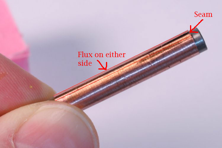
To form the cylinder, I rolled it around the smooth end of a 5mm drill bit and then used the smooth end of another drill bit to burnish the seam edges flat. Once in the proper shape, I plugged in the iron and while that was heating up I used my ratty old 5/0 brush to apply a thin line of liquid flux to either side of the seam. Liquid flux is a sticky mess so be careful not to spill it. As mentioned above, the flux helps molten solder flow so, while unnecessary for this example, careful application at this stage will help prevent the lose of detail and save you extra cleanup later. |
|
|
|
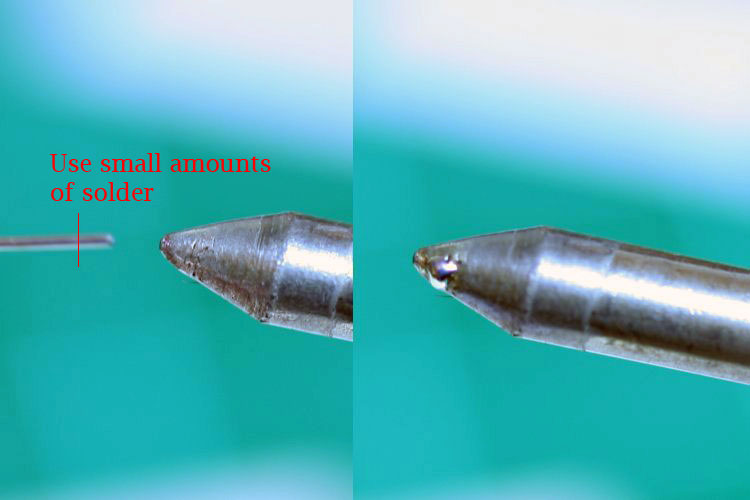
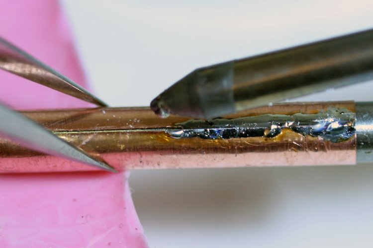
Once the iron is hot (test it by touching solder to the tip), you’re ready to bond the seam. I've read several different approaches to applying solder but the one that works best in my opinion is quite simple. I find that “pre-loading" the soldering iron (left picture) with a small amount of solder helps to control how much solder is deposited when the iron heats up the metal.
|
To pre-load the tip, melt a little core-less solder on the tip of the iron. Less is more here. If you've just tinned the iron you may not need to pre-load the iron the first few times. If you're about to touch a freshly tinned tip to a delicate PE part, test first on some fret. Once you're sure the tip is properly loaded, touch it to the fluxed area of the metal. When the metal heats up the flux will burn out and excess solder on the iron flows to the fluxed areas of the metal. How much solder you load on the iron determines how much ends up on the part - its better to go easy at first. The middle picture shows how the solder is worked over the cylinder's seam. Pinching the cylinder closed with a pair of tweezers, I drawing the iron tip across the seam to fill it in. Before the solder is completely unloaded you will notice that it stops filling in the seam gap even though it continues to deposit solder where there is flux. If you look closely at the middle picture you can see only about half of the area soldered so far has its seam filled in. The area on the left still shows the seam gap between soldered edges. Simply load up a little more solder on the iron and rework this gap to fill it in. A couple trips reloading the iron with solder and you end up with the part in the picture to the right.
|

|

|

|
Cleanup of the cylinder is simple, a file easily removes excess solder. Because solder is much softer than the metal it bonds, you can actually feel when you've filed down to the base metal.A little steel wool polishes everything up to a nice smooth finish.
|
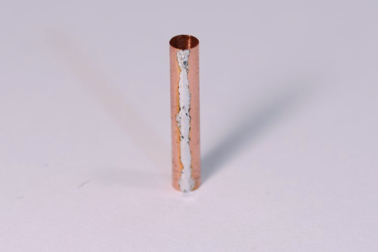
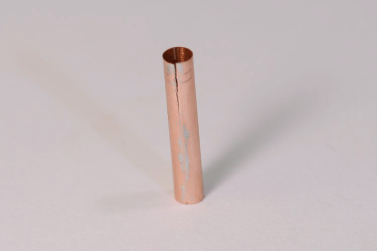
The picture on the left shows what happens if you're too aggressive with the filing. The copper actually cracked (not the solder joint - note the jagged edge). Fixing this sort of thing is easy. Simply reapply flux, re-solder, and re-file with greater care. The second picture from left shows the finished piece. The second picture from right shows an end view with a quarter on the left for scale. Minus the time to take photos, I think this took about 10 minutes to complete, including the time needed to repair the crack in the left picture. To get an idea of how much you can stress this joint, take a look at the picture on the right. It shows two cylinders with some "battle damage". The bottom cylinder has a miniscule hairline crack on the left side of the seam but I was unable to get it to show in the photo. It's so small that a coat of paint will fill it in though. I seriously doubt that a CA glued part could stand up to this kind of stress.
Fenders
|
|
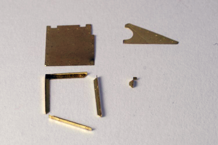
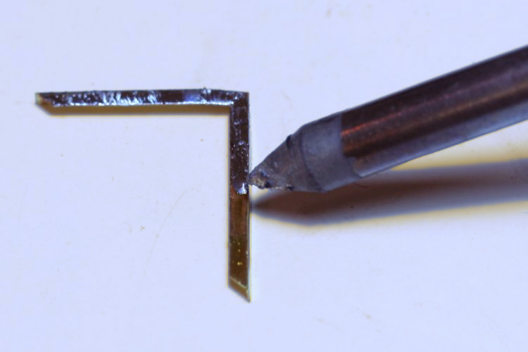
Because the fender was much more complicated in assembly (left picture) and had surface detail I did not want to cover, it required a little more care in applying the solder. The smallest part is also only about 3mm wide so this too posed a challenge. The best way that I found to assemble these parts was to tin one of the two to be joined. Flux was brushed along one surface that would form the joint and the iron was loaded with solder as in the cylinder example.
|
Simply drag the iron across the fluxed areas to deposit a layer on this half of the joint (right picture). If you apply too much solder, it's a simple matter of filing or using the solder bulb to suck up the excess. Since most often two parts that will be joined need to sit flush, take a little extra time with this step to ensure you get a thin and even coat of solder. I didn't in this example as you can see by the rough coat in this picture (note the bumps in the solder). As long as the coat is thin and you don't apply too much flux to either part, you won't need to fear detail being flooded. If the coat is uneven though, you might have positioning problems like the ones below.
|
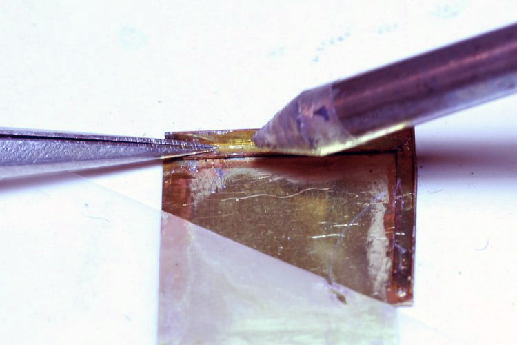
Once the top part was tinned, only flux was applied to the bottom part. No solder was used on it. Flux was also reapplied to the tinned part. The two parts were then positioned, and heat was applied. When sandwiching two parts together like this it's hard to tell when the solder is melting so look for the rosin to bubble and/or smoke slightly. Once this happened, I "walked" the iron over the length of the joint to get a good solid bond along the entire edge. Because I had failed to put a smooth thin coat of solder on the top part it rocked back and forth and was hard to keep positioned properly.
|
The tweezers were use to hold it as still as possible but when the solder melted, the top part settle down slightly out of position. To fix this I simply reheated the joint and moved the top part into position with the tweezers - in hindsight a steel ruler would have worked better for this. To avoid this extra work, I should have lightly filed the top part before trying to join it to the bottom. Spending a little time up front to make sure you get a good thin coat of solder will save you a lot down the road. Imagine if this had been in an area with several different solder joints very close to one another. I might have risked melting the others and possibly creating a lot of extra work. Heat undoing previous work is one of the biggest challenges in soldering but I have to say (to date) that none of my joints have come undone while heating something else. I think using the ceramic tile as a work surface has a lot to do with keeping things cool. In fact, if you look at the picture you'll see a piece of scotch tape holding the top surface of the fender in place while I solder the frame (the transparent diagonal bottom left). Even being only a few millimeters away from hot brass I had no trouble with the tape melting. In the picture below and on the left, notice how the brass has annealed only very closely to where solder was applied. I think the tile kept the rest of the fender cool enough. I've heard that some people use Blu Tac to hold parts and shield from heat as well.
|
|
|
|
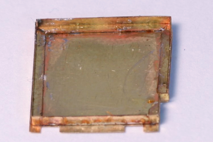
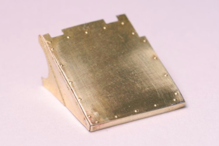
The rest of the fender was soldered in the same way as the first two pieces. These pictures show the assembly in various states of completion. The picture on the left shows the five parts assembled just before adding the final triangular piece.
|
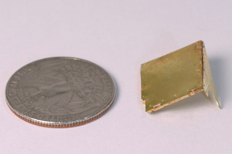
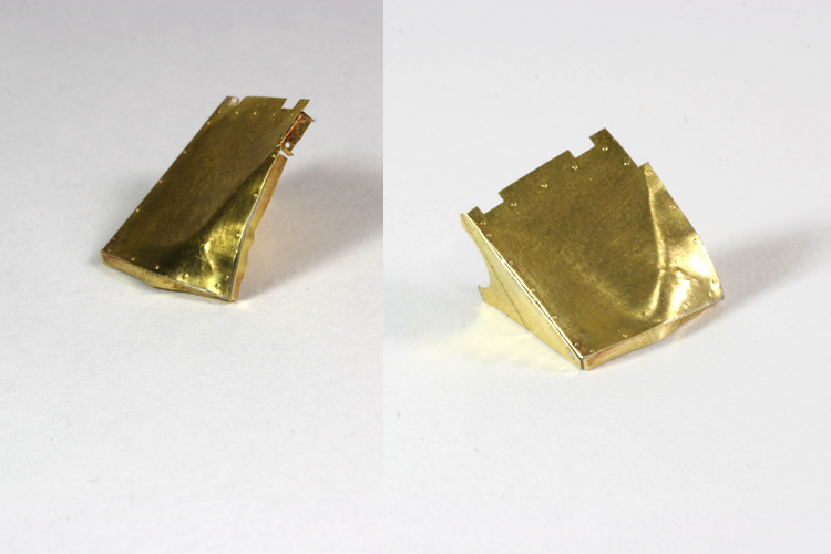
You can see how the right side is out of square here. To attach the last part of the fender I tinned the triangular piece along its contact edge. Flux was applied to both the triangle and the frame. Scotch tape was used again to hold the triangle in place on the tile. The frame was positioned upright on the triangle and tweezers were used to hold it in place as the iron heated the joint. I was afraid I might melt the previous solder of the frame but this ended up to be unfounded. The picture second from the left shows the part after assembly but before cleanup - the quarter for scale. The picture second from the right shows the finished part after a quick steel wooling. The picture on the right shows what kind of stress the soldered joints can take. Notice how they are is still in tact around all the seams. This just wouldn't be possible with super glue.
|
|
|
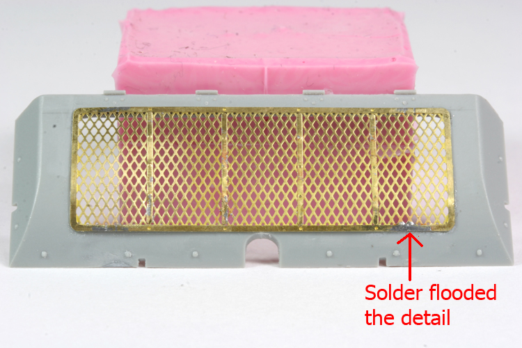
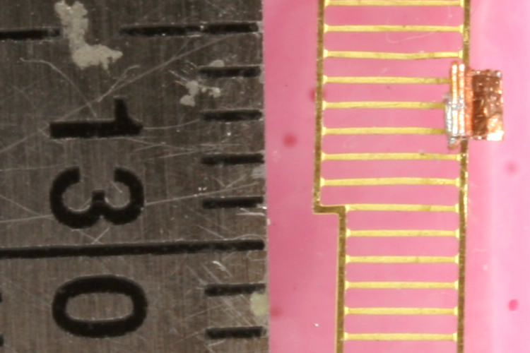
Here are a few images showing where I got started with all of this. These are all parts for a T-34 I'm working on for the Indianapolis AMPS group build. The grill in the left picture (made up of 6 pieces) was actually my first attempt at soldering PE. You can see in the bottom right of the grill an area where I used too much flux.
|
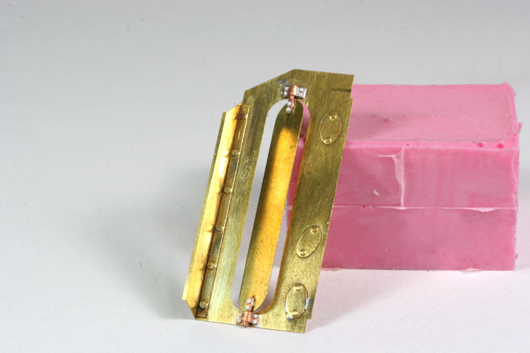
The solder ended up flowing into the grill covering up a few holes of the mesh - lesson learned. The photo in the middle is a ten part assembly. The oval cooling fin actually rotates and the hinges were soldered with the fin in place - heat wasn't a problem using the RTV rubber scrap. The small oval cover on the bottom right shows the effects of to much solder on the iron. A little filing and steel wool cleaned it somewhat but I was more careful on the other two. The right photo was an attempt to see if I could solder something very small (those are millimeters on the ruler). Soldering this hinge (copper rectangle in the top right) to the PE frame was no more difficulty than any part of the fender example above. I just used a little extra care to ensure a thin even coat of solder. The steel ruler was used to hold the hinge in place while I applied heat from the iron. Although you can make out a little excess solder at the join, this only appears in the photo and isn't noticeable with the naked eye.
Although there is certainly room for improvement, I'm really pleased with how well everything has turned out. Soldering PE really was a lot easier than I had thought. There really are only a few basic rules to follow: use a brushable flux and core-less solder, use small amounts of solder and flux for the bonds, and tin parts with a thin even coat before joining them. Using these, consistently good results were well within my grasp. I hope the examples have been clear and useful, but more importantly, hope the article motivates you to give soldering a try. The benefits far outweigh the extra time. For about the cost of a PE set you can get the tools needed to get started. Chances are you have PE "left overs" in the closet that you can experiment on.
Although there is certainly room for improvement, I'm really pleased with how well everything has turned out. Soldering PE really was a lot easier than I had thought. There really are only a few basic rules to follow: use a brushable flux and core-less solder, use small amounts of solder and flux for the bonds, and tin parts with a thin even coat before joining them. Using these, consistently good results were well within my grasp. I hope the examples have been clear and useful, but more importantly, hope the article motivates you to give soldering a try. The benefits far outweigh the extra time. For about the cost of a PE set you can get the tools needed to get started. Chances are you have PE "left overs" in the closet that you can experiment on.
For an example of how much is possible with photoetch, take a look at Rick Lawler's M2A1 over on Planet Armor - this is insane!
If you have questions, corrections, etc, feel free to contact me.
Happy modeling.
If you have questions, corrections, etc, feel free to contact me.
Happy modeling.
