Build Review of Tamiya 1/35th Scale KV-II "Gigant"
Series 63, Kit no. MM-183
By Ray Mehlberger
The in-box review of this kit appears in the Armor articles section here on Indy AMPS.
By Ray Mehlberger
The in-box review of this kit appears in the Armor articles section here on Indy AMPS.
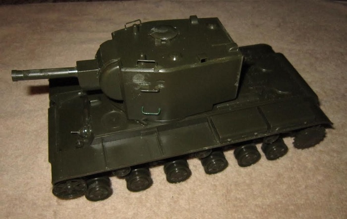
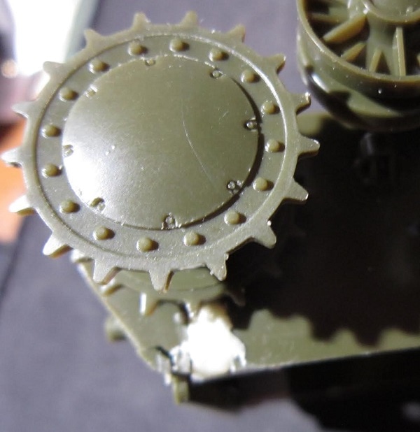
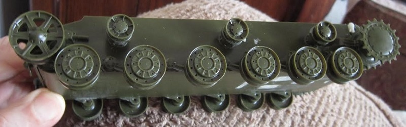
Starting with step 1 (naturally), I glued the two halves of the 2 idler wheels (parts B5 & B6), the two halves of the 12 road wheels (parts B9 & B10) and the two halves of the drive sprockets (B7 & B8), leaving the poly caps out of the centers of them. These caps are intended to make the wheels turn able after pressing them onto the axles for mobility if the kit was a motorized one. I glued them onto the hull tub solid, as I want the kit to be a static one.
In step 2 you opt to make the crew figure by just using his torso and separate arms, if you intend to pose him in the drivers overhead hatch or the turret hatch. His parts are not numbered as they are pretty obvious what they are. He can be used atop a seat (part no. C20) in the drivers compartment or atop a seat (part no. C21) in the turret.
Otherwise you can add his lower body part and pose him standing outside the tank.
Also, in this step you add the idler wheels, drive sprockets and 6 return rollers halves (two of part B2 each) glued to the hull tub with six axles (part B1). The curved rear hull wall (part A5) and two tow brackets (part C18) with tow rings (C13) are attached to this rear wall. The idler wheels are held on with seperate axles (A18). Be careful, because this part is easy to miss.
In step 3 I glued the 12 road wheels onto the hull tub and a plate (A7) to the nose of the tub, with 2 more tow brackets (C18) and tow rings (C19) added to this plate.
In step 4 you assemble the drivers compartment hatch. It is composed of the lid (C21) and hinge assembly (part C13 and (C15). I lost part C15, so decided to pose this hatch shut. The lid should have been labeled C12 and not C21. A curved plate (A14) was glued underneath the rear of the hull roof part and a nose piece (A4) added to the front of the hull roof.
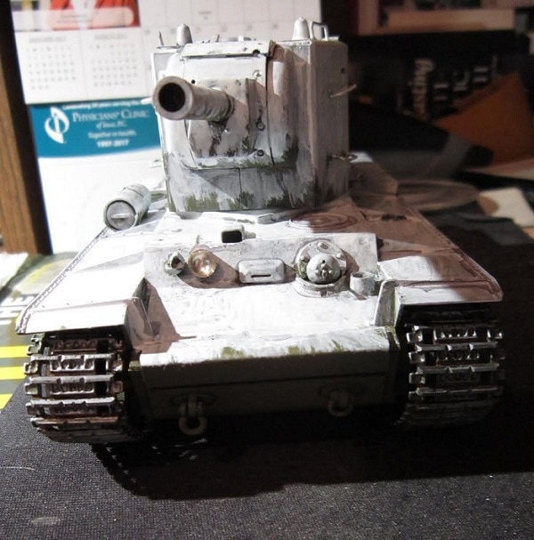
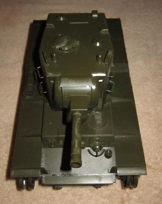
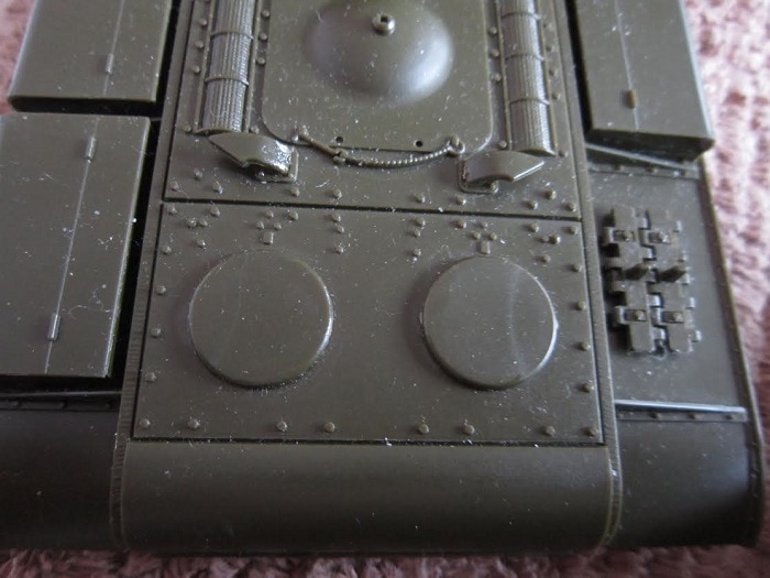
In step 5 I assembled the external fuel tank halves (A8 & A9) and their end caps (A3) and glued them to the fender tops. Three storage lockers (C38) were also added to the fender tops. Two vent domes where added to the top of the engine deck (C9) and 2 exhaust stubs (C6 & C7). A spare track link was added atop the fend too (A1). A ball mounted machine gun (Parts C39, C27 & C28) was added to the front wall of the drivers compartment, along with the siren (C29). I held off adding the headlight cup and it's lens (parts C22 & C23) until I add a MV glass lens to the cup. C22 is a molded solid lens that I prefer not to use. Two tow cable attachment bars are added to the sides of the hull roof (C16).
In step 6 you assemble the hatch lid (C5) and the locking handle (C1) and the hinge apparatus (parts C4 & C5) to its bottom. However, I found that this hinge did not operate well at all and decided to just glue the hatch shut.
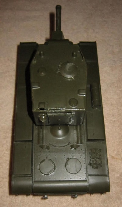
In step 7 you assemble the mantle (C37) onto the front of the trunion (C34) and then add the two halves of the main gun barrel (C32 & C33) and the muzzle brake (C30). The trunion is then trapped between the two turret halves (C11 & C17) and allowed to move with no glue added. Six glab handle/foot steps (C8) were then added. Two on each side of the turret and one on each side of the top of the roof. I managed to loose one of these and fabricated a new one out of wire stock. The turret roof (C31) was attached too.
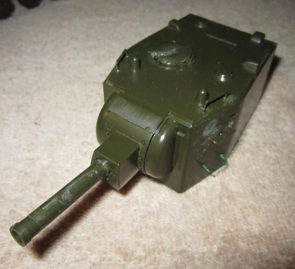
In step 8 the turret rear wall (C35), its rear door (C36) were added. The ball mounted machine gun (Parts C24,C25 & C26) were assembled and added to the rear turret wall. I lost the gun barrel C26 and fabricated a new one out of stretched sprue.
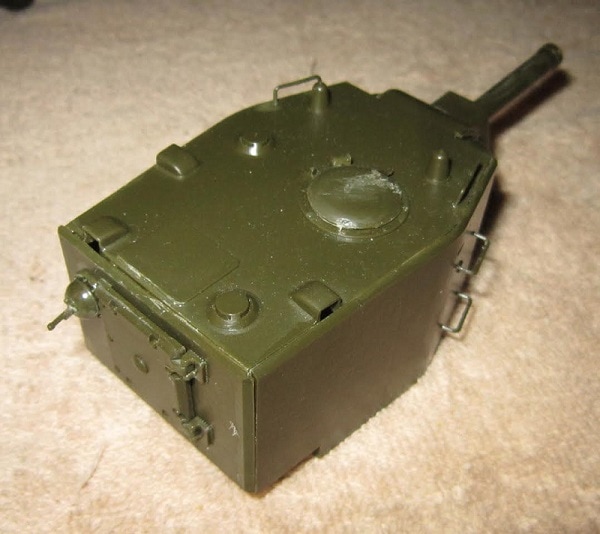
In step 9 you are shown to stretch some sprue to make a radio aerial and add it. An illustration shows you to use a heated mosquito coil to warm the tow cable (A2) to drape them over the fenders after attaching one end to the tow rings. The hull roof and hull are now joined and the turret screwed onto the top of the hull roof.
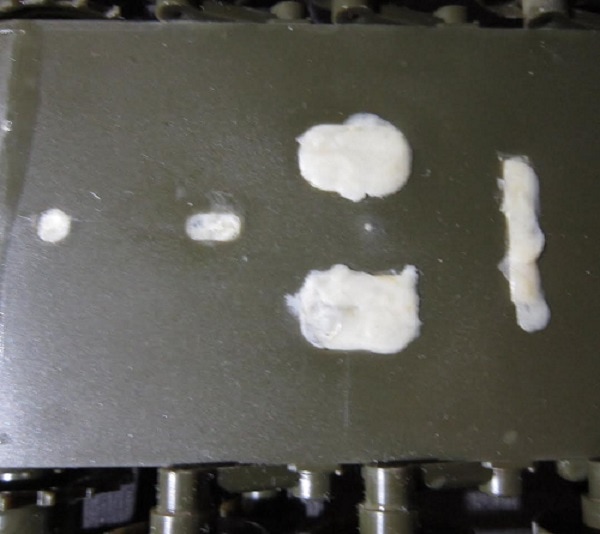
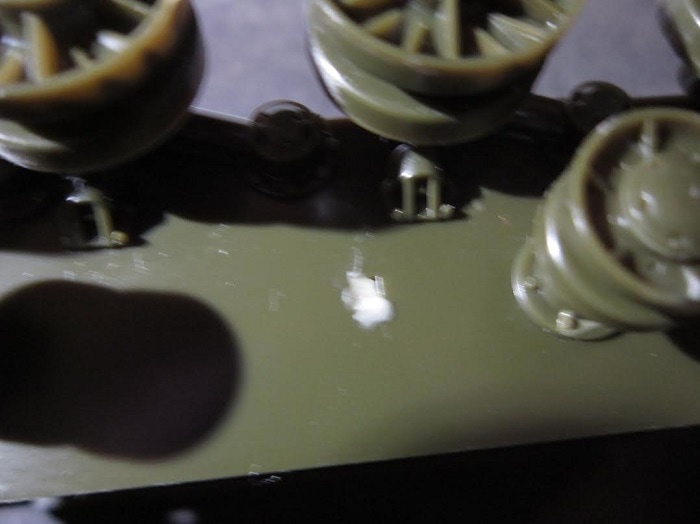
Next I puttied up the motorization holes in the bottom of the hull tub and the hole above the drive sprocket with Apoxy Scult putty.
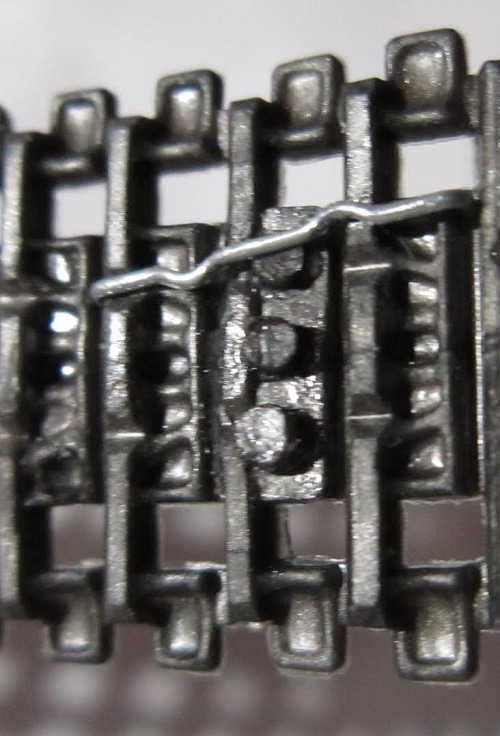
The vinyl tracks had a kink in each run. I put the kink under scalding hot water and straightened it out. I then put the one end of the runs over the three pins on the other end, super glued the connection and then stapled it. I stretched the loop over the running gear positioning the joint at the top, under the fenders to hide it.
Finishing the model:
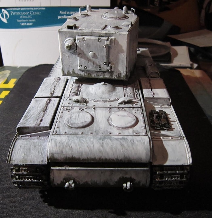
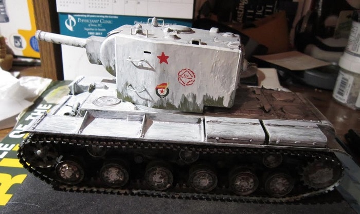
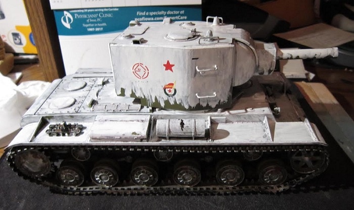
After assembling the model I sprayed it with an aerosol can of dark green Testors paint and then went over it with a winter white wash using Tamiya XF-1. I put flat black and red brown on the treads and then dry brushed them a little with steel enamel paint. I added the MV reflector lens to the headlight.
For the markings I used decals from Archer Fine Transfers. The circle mark says the tank is with the 109th Tank Brigade, 16th Tank Company. With the marking of the Order of the Red Banner and a Soviet red star insignia.
This was a easy build. Definitely a weekend project as it did not take very long.